



Island mode in practice
What is needed to make island mode work and ensure the earth electrode is correctly installed and tested?

What is needed to make everything work?
What is needed to make island mode work and ensure that the earth electrode is correctly installed and tested?
1. Solar PV system with battery storage
A complete solar PV system equipped with battery storage to store surplus energy. It is essential that the inverter used is approved for island mode, which means that it can power a local electricity grid without being connected to the public electricity grid. Some advanced inverters also have functions for automatically switching between grid connection and island mode, as well as managing load prioritisation and synchronising different energy sources.
2. Backup power changeover switch (ATS – Automatic Transfer Switch)
A backup power changeover switch is used to disconnect the property's electrical system from the public electricity grid during a power cut and switch over to backup power (e.g. a solar PV system with a battery). This switch can be manual, with the user activating the changeover, or automatic (ATS), which detects a power cut and switches over without manual intervention. The switch ensures that no electricity is fed into the electricity grid during island mode, which is essential for personal safety and to protect technical equipment.
3. Measuring equipment (earth electrode tester)
To ensure that the earthing is correctly installed and meets current safety requirements, an earth electrode tester is required. Examples of equipment include the Metrel MI3152 together with the Chauvin Arnoux earth electrode kit 1, a popular and reliable combination. This equipment can be used to measure earth electrode resistance and verify that the resistance is low enough to protect people and equipment in the event of a fault.
4. Earth electrode, electrical equipment & tools
-
Earth rod:
Used to create effective earthing.
These are usually made of copper or galvanised steel and should be at least 1.5 metres long to reach sufficiently deep into the ground. -
Copper conductor:
A copper conductor is used to connect the earth rod to the main earthing bar in the consumer unit. The conductor must have a sufficient cross-sectional area to withstand any fault currents.
-
Clamps:
Corrosion-resistant clamps are used to secure and maintain good contact between the earth rod, copper conductor and other connection points.
-
Electric breaker hammer:
An electric breaker hammer with sufficient impact force is used to drive the earth rod into the ground. The machine should be fitted with an SDS Max adapter or similar to drive the earth rod efficiently to the required depth.
What requirements apply to the earth electrode?
Earth electrode for island mode in solar installations
The earth electrode must have a resistance of no more than 100 Ohms to ensure correct protective earthing in island mode. This reduces the risk of electric shock and protects both people and equipment.
In island mode, a reliable earth electrode is especially important because the protective earthing for the entire installation depends on this point. Correct sizing, installation and regular testing are essential for safe operation.
Construction
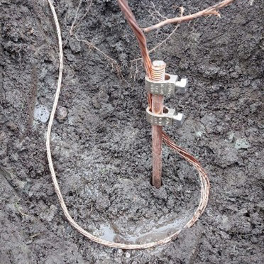
The earth electrode usually consists of one or more earth rods (at least 1.5 metres long, made of copper or galvanised steel). If necessary, several rods can be connected in parallel and placed at least one rod-length apart to reduce the resistance. Alternatively, a buried earth conductor can be used. When installing an earth electrode, the aim should be to achieve a low and stable earth electrode resistance. The best resistance values are obtained in damp ground, clay soil or topsoil.
Connection
The copper conductor to the main earthing bar should have a cross-sectional area of at least 16 mm². All connections should be made using corrosion-resistant clamps to ensure long-lasting, reliable contact.
Measurement and inspection
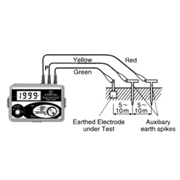
The earth electrode resistance must be measured using an approved earth resistance tester (e.g. four-terminal measurement in accordance with SS-EN 62305-3) after installation, and the results documented. The measurement must be repeated at least every eight years, or whenever changes may affect the earthing system.
Electricity grid operator requirements for backup power operation*
*Please note that some local requirements may apply. Always check with your local electricity grid operator before starting the installation.
When an installation is designed to operate in island mode (e.g. with a solar PV system and battery or a backup generator), the electricity grid operator sets clear requirements for how the earthing must be installed and how the installation must be connected to the electricity grid:
-
Separation from the electricity grid
In island mode, the installation must be completely disconnected from the public electricity grid. This is done using a grid changeover switch that ensures no electricity can be fed into the grid while operating in island mode. This is a safety requirement to protect both personnel and equipment on the electricity grid.
-
Earthing and earth electrode
In island mode, the installation must have its own earth electrode, dimensioned so that its resistance is sufficiently low (often no more than 100 ohms). The earth electrode must ensure that protective earthing works even when the installation is disconnected from the electricity grid. The resistance must be measured, documented and checked regularly (every 8 years).
-
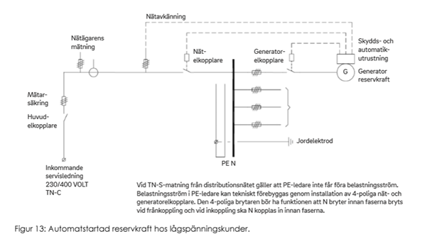
The PE conductor must not carry load current
For a TN-S supply (separate protective earth and neutral conductors), the PE conductor (protective earth) must never carry load current. This is achieved by using four-pole switches for both the grid and generator connections. These switches must disconnect the neutral conductor (N) at the same time as the phase conductors, and when connecting, N must be connected before the phase conductors. This prevents current from flowing through the PE conductor and thus ensures correct protective earthing.
-
Changeover/disconnection
When operating on backup power (e.g. a generator or an inverter for island mode), changeover between the grid and backup power must be arranged so that there is never any risk of parallel operation or backfeeding into the electricity grid. The changeover must also ensure that earthing is correct in both operating modes.
-
Documentation and inspection
The earth electrode resistance must be measured and documented at installation and then regularly thereafter (at least every eight years). All documentation must be retained and made available for inspection by the electricity grid operator or an authorised installer. Note that many electricity grid operators require a single-line diagram for backup power installations.
In principle, this applies from the electricity grid owner
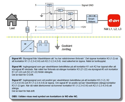
This could be a Huawei Backup Box, Fronius Enwitec, or other inverters capable of island mode. The signal and input numbering in this image is from Fronius, but it should be equivalent for other brands.
[***] A TN-S system must have two additional contactors connected in parallel to connect Neutral to Earth (PE) when the grid is lost. These must also have an extra contact to feed signal input 6. Contactor K1 (7-8) and K2 (7-8) must also disconnect Neutral in a TN-S system.Backup power changeover switch
Manual
Manual changeover – a changeover switch is installed, which you turn manually to connect to or disconnect from the distribution network.
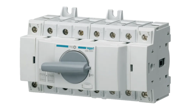
Automatic
An automatic changeover switch is called an ATS (automatic transfer switch) in English. It consists of several relays
Full backup or partial backup
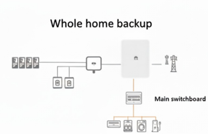
When sizing a system for backup functionality, you need to consider what you want to power and for how long. This is crucial when deciding whether to provide backup for the entire house/property (full backup) or to select priority loads in a separate consumer unit for backup (partial backup).
Full backup
The customer's entire main consumer unit is energised and can be used during a power cut. The most common arrangement is for the inverter to supply power asymmetrically in island mode, allowing it to handle three-phase loads.
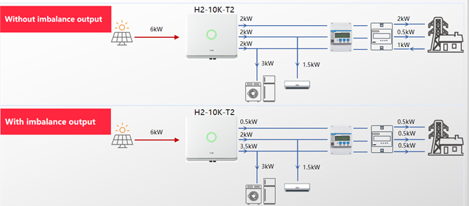
Full backup requires sufficient power from the inverter and battery, but also places extremely high demands on the capacity of the battery system in terms of the number of kWh and kW. The advantages are clear: the entire system seamlessly switches to backup mode. This places great demands on the inverter’s ability to power all the loads (having sufficient power for a “black start”) and on the system’s ability to handle the starting currents that electric motors, compressors, etc. may require. Without this functionality, the system will not work as intended.
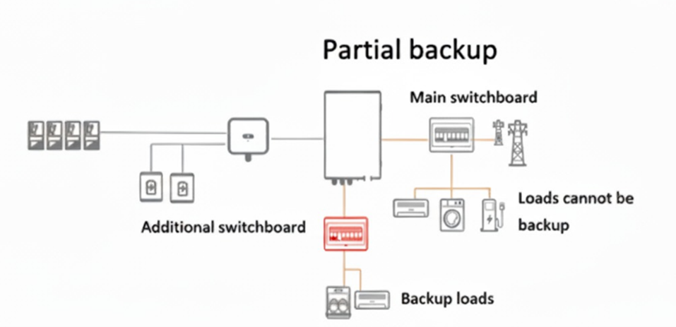
Partial backup
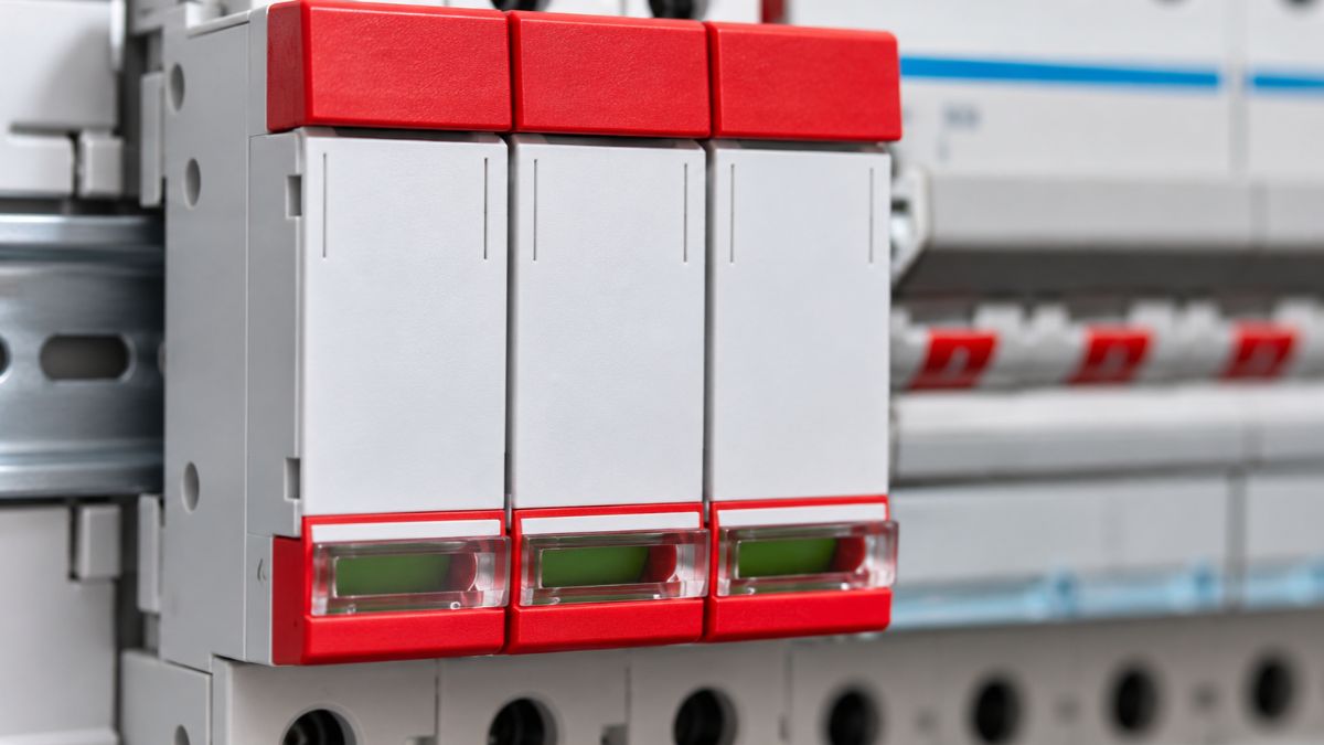
A separate consumer unit for smaller loads (priority loads) is energised by the inverter. The inverter can be a three-phase model (for example, Huawei M1 (3–10 kW)), but it can only supply three-phase power on one phase (phase 1). One advantage of this setup is that some loads are not connected to the priority single-phase circuits that have backup. This means the energy in the battery will last longer. The downside, of course, is that you cannot power three-phase loads and that you must physically rewire your consumer unit and put the priority backup loads in a separate consumer unit (see the unit shown in red below in the image).
Product-specific information
SAJ
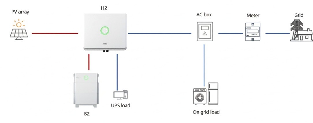
Partial solution
With the SAJ H2, partial backup is achieved by connecting priority loads to the inverter’s backup port. Note that full backup is possible, but requires a separate ATS box (see the next heading).
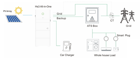
Complete backup
Using SAJ’s ATS box, full backup can be achieved with SAJ HS3 (all in one).
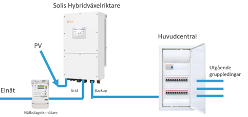
Solis inverters
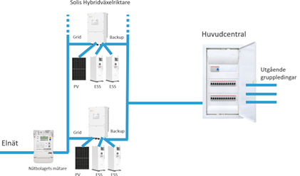
Solis inverters are hybrid models equipped with backup functionality and a changeover time of max. 10 ms (UPS functionality). Solis inverters have a built-in ATS, which means that no separate unit is needed to provide full backup. This can be used in the simplest case with one inverter, enabling full backup.
If the power requirement is greater, Solis enables parallel operation in island mode with several parallel hybrid inverters. A distribution busbar is set up on the incoming side, with all inverters connected to the grid, and then a distribution busbar on the backup port, from which the main consumer unit is supplied by all the inverters. Note that, for example, each 30–50 kW hybrid inverter can connect to two Dyness BF100 units, providing a capacity of 200 kWh. Up to 6 hybrid inverters can be connected in parallel in this configuration, and, of course, solar power can also be connected to the inverters.
Ferroamp
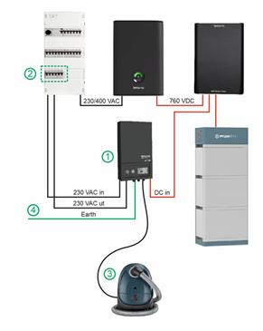
Ferroamp EmergencyPower 1P is a backup solution that makes it possible to power selected single-phase loads in the home during a power cut. The product works with Ferroamp’s EnergyHub system and batteries, and automatically switches between grid operation and backup power operation when the electricity grid goes down.
Main features:
- Power and capacity: Maximum output is 2.3 kW (10 A, 230 V AC, 50 Hz), which is enough to keep essential household appliances running during extended power cuts.
- Automatic changeover: The system automatically switches to backup power when the electricity supply is interrupted.
- Black start: Can start batteries and solar panels even from a completely powerless state.
- Easy installation: No conventional earth electrode is required, making installation simpler and less expensive.
- Backup control: Three modes – OFF, BYPASS and AUTO – to control when and how backup is used.
- Battery management: The system protects the batteries by shutting down when the state of charge is low (SOC 5%) and can be restarted when solar energy is available again.
- Compatibility: Works with Ferroamp systems with one EnergyHub and at least one battery (not for systems with multiple EnergyHubs or PowerShare networks).
- Single-phase only: The product supports single-phase loads only, not three-phase.
Huawei
Huawei’s solution for enabling island mode in three-phase systems is called Grid Guard. It is a complete solution that also includes Huawei’s Emma smart home gateway. In island mode, the system can automatically give lower priority to loads such as washing machines, electric vehicle chargers or heat pumps. To enable island mode in three phases, an inverter from the MAP0 series is required.
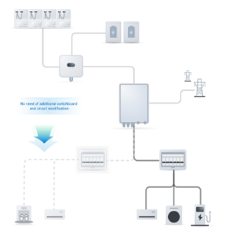
Below is a table showing all Huawei inverters, the type of island mode they support, and whether UPS support is available.
| Product series | kW | Battery-ready? | Island mode? | UPS |
|---|---|---|---|---|
| Huawei M1 | 3-10 | Yes | Yes, single-phase | No |
| Huawei MAP0 | 5-12 | Yes | Yes, three-phase | Yes |
| Huawei M2 | 12-20 | No | No | No |
| Huawei M5 | 12-20 | No | No | No |
| Huawei MB0 | 12-25 | Yes | Yes, single-phase | No |
| Huawei M3 | 30-50 | No | No | No |
| Huawei M0,M1,M2 |
60-150 | No | No | No |
How is island mode installed in practice?
Watch the video from Senergia Play below

Need help finding the right option?
We know it’s not always easy to know which product or solution is best for you. Whether you have questions about our range, need guidance or would like help finding a solution that suits your specific needs, we’re here for you. With our knowledge and experience, we’ll help you make the right choice.
Related posts
How do you install an earth electrode and set up off-grid operation – with Richard Nyberg
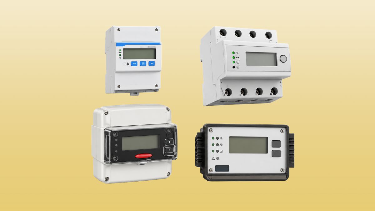
Smart meter, a smart electricity meter