




New rules for functional earthing
Introduction
In a short time, functional earthing has gone from being a niche issue for particularly interested installers to becoming a central part of how solar installations should be designed, installed and inspected. With new shared guidelines and clarified practice from the industry and authorities, we now need to update how we think about earthing metal parts in solar installations [2–4].
In an earlier post on Senergia’s technical blog, “To earth or not to earth – that is the question”, we discussed the uncertainties surrounding when and how earthing should be carried out in solar installations [1]. Since then, both the Swedish Electrical Safety Authority and industry organisations have taken important steps towards establishing more consistent practice—which means that some conclusions in older interpretations now need to be revised [2–4].
In this post, we explain what functional earthing is, why the rules and industry guidelines have been updated, how functional earthing is carried out in practice in a solar installation, and how you as an installer can check continuity in a structured way.
This blog post will explain why functional earthing is now needed (and why it should have been needed from the outset), as well as how installers carry out functional earthing and how it is checked.
Not functionally earthing your system and then expecting the inverter’s insulation monitoring to work is like requiring a residual current device in the installation but not requiring it to be connected. That is the fundamental difference in the industry’s new interpretation.
So, if you are reading this blog post looking for a short answer, you need not read any further. The answer is yes: you need to functionally bond the mounting system and the panels. For those of you who want to understand why and how to do it, we hope you enjoy the rest of the article.
Background
Functional earthing allows the inverter to detect leakage currents, for example from damaged cables or solar panels. This function is similar to a residual-current device. All inverters sold in Sweden must perform a daily insulation test, measuring any leakage current through damaged cables or panels and triggering an alarm if an insulation fault is detected.
However, if the mounting system and the panels’ frames are not connected to earth (functionally earthed), there is no reference point for the measurement. The inverter may have this function, but the installation still has no practical way of detecting the fault.
When an inverter starts up, it performs insulation measurements on both the positive and negative poles of the system to detect whether either of them is in contact with earth.
For insulation monitoring to work correctly with faults other than just series insulation faults—which the inverter can detect—the mounting system must also be functionally earthed. Otherwise, a parallel fault current may go completely undetected.
Which regulations apply?
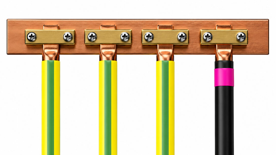
The functional earthing of the mounting system and solar-panel modules must be equipotentially bonded to, for example, the inverter chassis or an earthing block. The Electrical Installation Regulations specify that this should be done as close to the inverter as possible. Note that not all inverters support earthing via the chassis. So take care to ensure it functions correctly. For more information, see Chapter 712 of the Electrical Installation Regulations.
When you, as an installer, carry out an insulation measurement, it is crucial that you measure correctly to ensure the result is reliable. If you only measure to earth at the inverter, you may get a reading that gives a false sense of security, because in practice the reading is incorrect. If you do not know exactly what you are measuring, it is easy to trust the instrument blindly, even though it is showing something that is not right.
Handbook 457 is therefore not sufficient for finding the right answers in this context; Chapter 712 of the Electrical Installation Regulations applies. Manufacturers often settle for stating that the function is available, but responsibility then lies with the installer to understand how everything should work in practice—and unfortunately, that is often where things fall short. Senergia’s Technical Blog would also like to add that many manufacturers should be much clearer that their insulation monitoring function does not work without an earth reference on the mounting system and panels. At Senergia, we are working actively with our suppliers to ensure that this is stated explicitly in manuals.
If the functional earth is not correctly installed, it is also impossible to measure continuity in the way required by standard 62446-1. A series arc disappears when the voltage is disconnected, but a parallel arc is much more difficult to deal with. That is why you should always make a habit of equipotential bonding in accordance with the new industry regulations.
What is functional earthing?
Functional earthing (or functional bonding) is a connection to earth or an equipotential bonding system whose primary purpose is not personal safety (protection against electric shock), but to ensure that an electrical function operates correctly and reliably [2,3].
In solar PV systems, functional earthing is often used to:
- ensure that the inverter’s insulation monitoring operates reliably, by keeping metal parts at a defined potential relative to earth [2,3],
- provide a stable earth reference to make it easier to detect insulation faults on the DC side,
- reduce the risk of interference, false indications and sporadic alarms from the insulation monitoring system.
It is important to distinguish between:
- Protective bonding / protective earthing
Its purpose is personal safety – to prevent live parts from coming into contact with enclosures or other accessible metal parts in the event of a fault. - Functional bonding / functional earthing
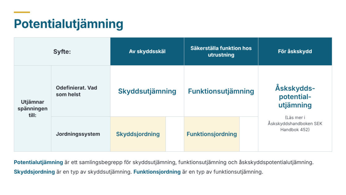
Its purpose is functional – in solar PV systems, for example, to ensure that insulation faults are detected, not to create a protectively earthed enclosure [2,3]. The industry association Svensk Solenergi clarifies the different types of bonding and earthing that can be carried out in an electrical installation. The illustration below explains this.
For solar PV systems, industry guidelines emphasise that protective bonding should not be carried out on metal parts on the DC side, as the installation is double or reinforced insulated [3]. Instead, functional earthing is connected to the property’s earthing system when required to ensure correct operation [2,3].
Background – from Senergia’s earlier blog posts to updated regulations
When we previously wrote about the question of “to earth or not to earth”, it was at a time when:
- The wording of the Electrical Installation Rules on equipotential bonding and insulation monitoring was considered unclear when taken out of context [3].
- Manufacturers’ instructions varied – some clearly described when metal parts should be earthed, while others left considerable room for interpretation [3].
- Installers and inspectors could reach different assessments of virtually identical installations [1–3].
Since then, the industry, together with the Swedish National Electrical Safety Board, has developed joint guidelines for functional earthing/functional bonding in solar installations [2–4]. The work was carried out as an open industry collaboration involving, among others, Installatörsföretagen, Svensk Solenergi, SEK Svensk Elstandard and the Swedish National Electrical Safety Board, with the aim of establishing more consistent practice [4].
However, what was mentioned earlier in Senergia’s technical blog post is still highly relevant and correct. Functional bonding of the mounting system contributes to the following benefits:
-
Insulation monitoring
Solar installations must be isolated from earth because solar cells are Class II equipment. The insulation resistance must therefore be monitored continuously using an IMD. If the resistance becomes too low, the inverter must issue a warning. This function is usually built into the inverter; otherwise, it must be added. The measurement is taken between positive/negative and earth, which requires a defined earth potential (zero level).
-
Arc-fault detection
Arc-fault detection (AFCI) is becoming increasingly common and is now built into many inverters. A sensor analyses the DC circuit and uses algorithms to identify arcs. When an arc is detected, the inverter throttles production, extinguishing the arc.
-
Reduced EMC issues
Functional earthing in installations with optimisers reduces EMC issues. Earthing the rail system dampens high-frequency signals. Put simply, functional earthing acts as a shock absorber that “quells” certain electromagnetic interference.
Another part of the background is that the Swedish National Electrical Safety Board has clarified that reliable detection of insulation faults is central to preventing faults that can lead to fires, a point also highlighted in its report on fires and fire incidents in solar installations [4].
Taken together, this means that the new guidelines and descriptions of practice are a direct response both to practical experience from the field and to statistics on fire incidents in solar installations [3,4].
How is functional earthing carried out – and how is continuity checked?
Principles of functional earthing in solar PV systems
The updated industry recommendations clarify that [2,3]:
- the purpose of equipotential bonding is to improve the connection to earth, so that insulation faults can be detected reliably,
- when equipotential bonding is required on the DC side, this is in practice functional earthing/functional bonding to the building’s earthing system – not protective bonding.
The new recommendations mean that installers functionally earth the metal parts of solar PV systems – such as mounting systems, panel frames and metallic containment – to ensure that the inverters’ insulation monitoring works as intended [3]. Equipotentially bonding these metal parts increases the likelihood that insulation faults are detected in time [3].
Practical implementation – a typical installation sequence
To ensure that the metal parts in the installation are at the same potential, they must be connected together. This can be done in various ways and depends on the type of solar panel, mounting system, electrical equipment (such as cable trays, etc.) and the type of roof on the building. A typical functional earthing solution for a roof-mounted solar PV system may include:
- mounting rails and supports that are electrically interconnected (for example, using rail connectors, earthing clamps or integrated contact plates),
- solar panel frames with a defined electrical connection to the mounting system via approved clips or bolted connections,
- metal cable trays, trunking and any protective conduits included in the DC cable routing, connected to the same functional bonding system [3],
- a functional earthing conductor connecting the mounting system to the building’s earthing system (the main earthing terminal or another suitable connection point specified in the design) [2,3].
Important points for the installer:
- Always follow the inverter and mounting system manufacturer’s instructions on whether and how their products should be earthed [3].
- Ensure that mechanical connections intended to carry current also provide a secure electrical connection (for example, avoid insulating layers, use approved clamps and check tightening torque).
- Keep DC-side functional bonding separate from any AC-side protective bonding – they have different purposes and are subject to different regulations [2–4].
Where should I connect my functional earth?
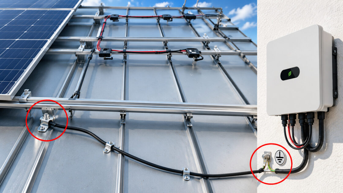
Functional earthing should be connected as close to the inverter as possible. Sometimes it may also be appropriate to connect it to an earth terminal in the installation’s distribution board – that is, the terminal where the other earthing conductors are connected. The functional earth is connected to the same earth terminal as the other earthing conductors (both protective earth and functional earth).
Continuity checks – a step-by-step method
To ensure that the functional earthing is doing what it should, continuity should be checked and documented. A structured method may include:
-
Visual inspection
- Ensure that all planned connection points have actually been installed: earthing clamps, joints, bonding conductors, transitions between roof and façade, etc.
- Check that no connections have visibly corroded or been damaged during installation.
-
Continuity measurement with a low-resistance meter
- Measure the resistance between different metal parts (for example, at the far end of the mounting rail) and the point where the functional earthing conductor connects to the building’s earthing system.
- Compare the readings with the design requirements and internal procedures – aim for low, stable readings that indicate a good metallic connection.
- Document the measurement points and results so they can be replicated during future inspections or fault-finding.
-
Functional check via the inverter’s insulation monitoring
- After commissioning, monitor how the inverter’s insulation monitoring behaves – for example, whether alarm thresholds are reached unexpectedly or the inverter issues recurring error messages.
- If insulation fault alarms recur, check the DC cables, connectors and functional bonding – inadequate functional earthing can make faults harder to detect consistently.
- Note that the inverter is not an approved measuring instrument, and checks before commissioning must be carried out using approved measuring instruments that comply with Swedish Standards and the requirements of the Swedish Electrical Safety Agency.
-
Periodic inspection and maintenance
- When servicing or extending an existing system, repeat the continuity measurement and visual inspection of the functional earthing.
- This is particularly important after roof alterations, replacement of panels or mounting systems, or when parts of the installation have been dismantled.
Functional earthing in practice
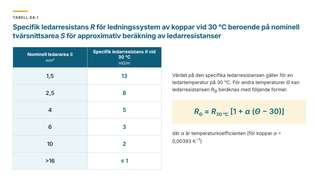
To ensure good functional earthing and good electrical continuity, you as an installer need to ensure that you achieve continuity and sufficient electrical conductivity. This must be measured and checked during pre-commissioning inspection.
Functional earthing of solar panels
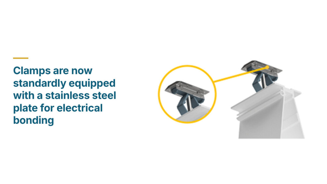
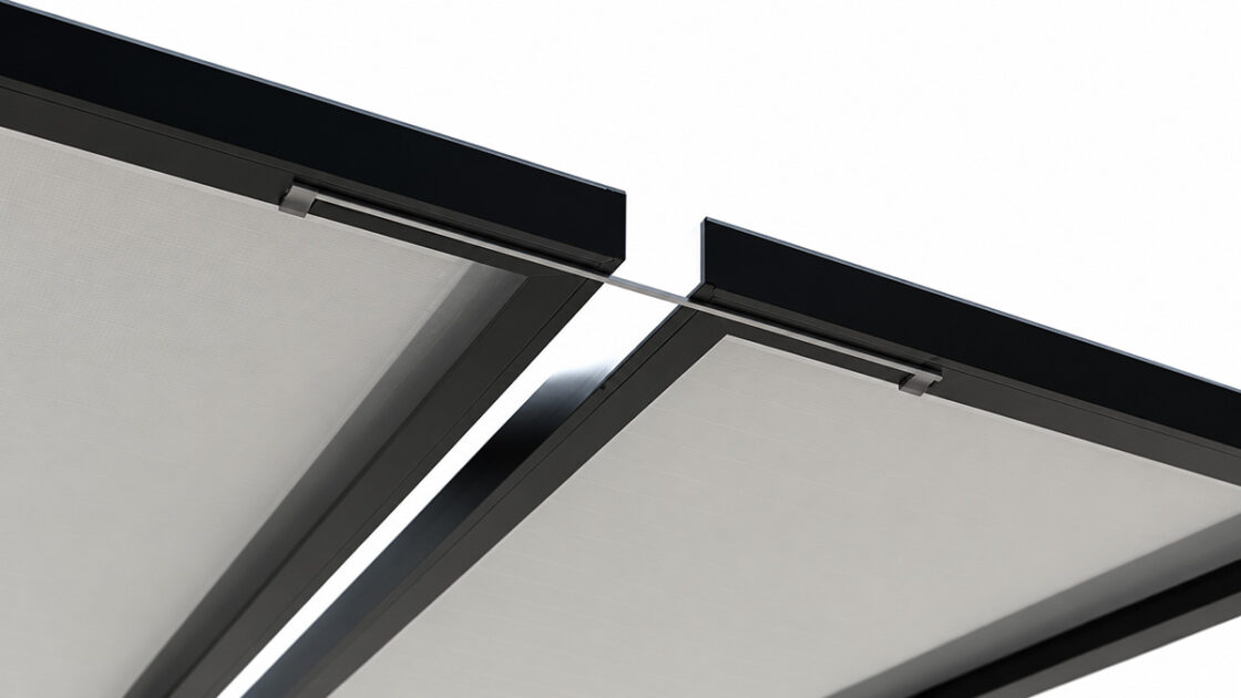
Depending on the type of solar panel used and whether it is made of anodised aluminium, which does not conduct electricity. Some manufacturers, such as Van der Valk (pictured below), have special clamps that break through the outer anodised layer to increase electrical conductivity and facilitate functional earthing.
If the solar panels cannot provide sufficient electrical conductivity for functional earthing, additional measures need to be taken. One example of such a measure is to electrically connect the frames using additional functional earthing conductors or a “bonding jumper”.
Functional earthing of rail systems
The mounting system and rail system are often made of steel (usually Magnelis ZM material) or aluminium. Both are good electrical conductors.
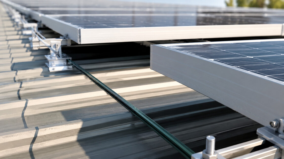
Remember that to achieve functional earthing of the entire mounting system, the following conditions must be met:
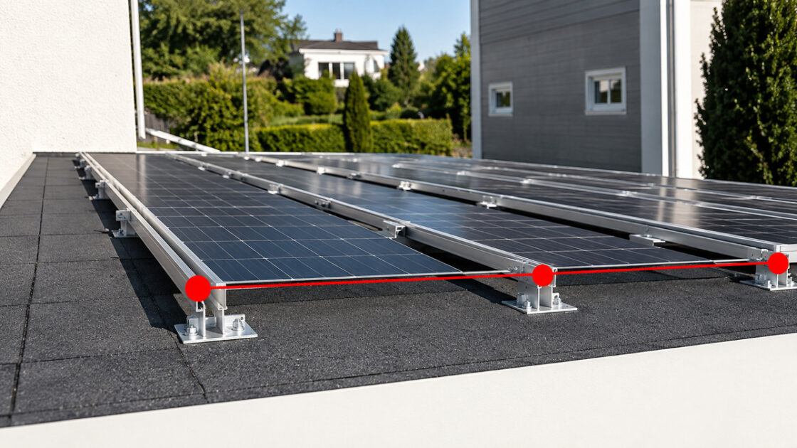
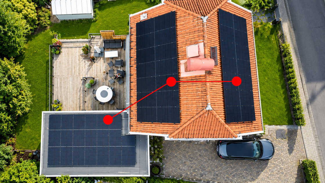
The rails within the same panel group must be functionally earthed. This is done either by connecting a single-core cable between each row of rails or by connecting sufficiently robust electrically conductive perforated strip between the rows of rails.
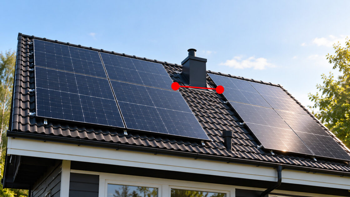
If the rail system is not connected to several groups of panels, a functional earthing conductor must be run between the panel groups. Note that this must also be done if thermal expansion gaps are provided.
Functional earthing of different panel groups
If a solar installation has several panel groups, they must either be connected together using functional earthing conductors, or all equipotential bonding conductors must be connected to a common earthing bar.
Functional earthing from the roof to the earth bar
When the mounting system and panels are functionally earthed, a conductor must be run and connected to the inverter chassis or earth terminal.
Summary and conclusion
The new guidelines and clarified practice regarding functional earthing in solar PV installations mean, in practice:
- a clearer industry-wide understanding of when and how functional earthing should be carried out [2–4],
- a strong focus on improving the reliability of insulation-fault detection, to reduce the risk of fire incidents [3,4],
- a clear distinction between protective equipotential bonding (which should not be used on metal parts on the DC side of double-insulated solar PV installations) and functional earthing/functional bonding [2,3].
For you as an installer, this means that:
- you need a well-developed functional earthing strategy from the design stage,
- you should follow both the manufacturers’ instructions and the industry-wide guidelines now developed,
- you need to make continuity checks and documentation a natural part of your own inspection procedures.
Senergia will continue to monitor developments in standards, regulations and practice, and update our recommendations as new experience and data emerge. In the meantime, our advice is:
- Plan functional earthing as carefully as cable and protection sizing.
- Measure, verify and document continuity in the functional bonding.
- See functional earthing as an important tool for both operational reliability and fire safety in modern solar PV systems.
References
- To earth or not to earth – that is the question [Internet]. Stockholm: Senergia: https://senergia.se/teknikblogg/inlagg-2-att-jorda-eller-inte-jorda-det-ar-fragan/
- Svensk Solenergi. Joint statement on functional earthing [Internet]. Stockholm: Svensk Solenergi: https://svensksolenergi.se/gemensamt-uttalande-om-funktionsjordning/
- Svensk Solenergi. Functional earthing of metal parts [Internet]. Stockholm: Svensk Solenergi: https://svensksolenergi.se/funktionsjordning-av-metalldelar/
- Elsäkerhetsverket. Clarified practice for solar panel installations [Internet]. Kristinehamn: Elsäkerhetsverket 2025: https://www.elsakerhetsverket.se/om-oss/press/nyheter/2025/fortydligad-praxis-for-solcellsinstallationer/
- Solar Grounding EXPLAINED: The CRITICAL Step Installers Skip (Costly Mistake!) https://youtube.com/watch?v=C7YXUzL5qE4&si=vVKTcSJw1qWiNNN8
Need help finding the right choice?
We know it isn’t always easy to know which product or solution is best suited to you. Whether you have questions about our range, need guidance or would like help finding a solution tailored to your needs, we’re here for you. With our knowledge and experience, we’ll help you make the right choice.
Related posts
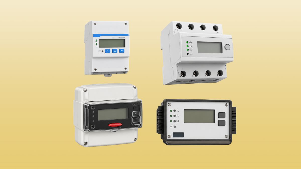
Smart meter, a smart electricity meter
surge protection device (SPD)